Input application for UGRAMM:
-
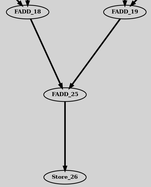
In a CGRA, the input application is usually represented as a Data Flow Graph (DFG), where vertices correspond to operations like ADD, SUB, and MUL, and the edges between these vertices indicate the dependencies among these operations.
-
UGRAMM comes with various CGRA benchmarks designed for HPC applications, including Convolution, FFT, and Stencil, with both Balanced and Unbalanced versions. Additionally, each benchmark type supports different unrolling factors ranging from 1 to 10.
├── Kernels
│   ├── Conv_Balance
│   │   ├── conv_nounroll_Balance.dot
│   │   ├── conv_nounroll.dot
│   │   ├── conv_unroll2_Balance.dot
│   │   ├── conv_unroll2.dot
│   │   ├── conv_unroll3_Balance.dot
│   │   └── conv_unroll3.dot
│   ├── Conv_nonBalance
│   ├── FFT-Radix
│   │   ├── FFT-Radix-4
│   │   └── FFT-Radix-5
│   ├── Stencil_Balance
│   └── Stencil_nonBalance
- These benchmarks are defined in the Graphviz DOT format (ref).
//Node/Vertex definition:
Load_0 [label="{Load_0}", opcode=input, shape=record];
FMUL_9 [label="{FMUL_9}", opcode=FMUL, shape=record, type=op];

//Edge definition:
Load_0 -> FMUL_9  [driver=outPinA, load=inPinA];
Required and optional attributes in application-dot file.
- As shown above, vertices and edges have specific attributes or properties. Some attributes are essential for GRAMM to function correctly.
- Node Attributes:
- label: [Required] Specifies the operation name in the application graph (e.g.,
[label="{Load_0}"]). - opcode: [Required] Specifies the operation’s opcode (e.g.,
[opcode="input"]). - placementX: [Optional] Specifies the fixed X-coordinate for node placement (e.g.,
[placementX="2.0"]). - placementY: [Optional] Specifies the fixed Y-coordinate for node placement (e.g.,
[placementY="5.0"]).
- label: [Required] Specifies the operation name in the application graph (e.g.,
- Edge Attributes:
- driver: [Required] Specifies the driver pin to use for the edge (e.g.,
[driver="outPinA"]). - load: [Required] Specifies the load pin to use for the edge (e.g.,
[load="inPinA"]). - Example:
Load_0 -> FMUL_9 [driver=outPinA, load=inPinA];- In this example, UGRAMM selects the
outPinAof the device-model node whereLoad_0is mapped and routes it to theinPinAof the device-model node whereFMUL_9is mapped. - For UGRAMM to function as expected, the device model must have nodes with pins defined as
outPinA,inPinA,B, etc.
- In this example, UGRAMM selects the
- latency: [Optional] Specifies the latency requirement for the edge (e.g.,
[latency="2.0"]).
- driver: [Required] Specifies the driver pin to use for the edge (e.g.,
- Node Attributes:
- The [Required] node and edge attributes must be clearly defined in the
application.dotfile when used as an afile input to ensure UGRAMM functions correctly.