Device model input:
-
The device model graph is a larger graph used to determine whether the application graph is a minor of it. As the name suggests, the device model dot file represents the graphical format of the hardware architecture onto which we aim to map the input application.
-
CGRA architectures such as RIKEN and ADRES can be converted into graphical dot format. To simplify the generation of graphical dot files of these architectures, we have created a script in
scripts/device-model-gen.pythat can easily generate a dot graph format file for standard CGRAs, and right now it supports RIKEN and ADRES architectures. -
The following section will explain how the script functions and how the architecture is represented in graph format, which may inspire the creation of a similar script for new GRAMM applications requiring automated device model generation.
Device model generation script:
- Usage:
device_model_gen.py [-h] [-NR NR] [-NC NC] [-Arch ARCH]- NR (Number of rows), NC (Number of columns), and Arch (name of architecture)
- Example:
./device_model_gen.py -NR 8 -NC 8 -Arch RIKEN - Generates a device model for the specified CGRA architecture.
- When the script is executed, the output will be saved as
<Arch_Name>_<NR>_<NC>.dot. - Architecture supported:
- RIKEN
- ADRES [Work In Progess]
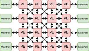
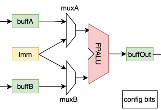
- Script generation example for RIKEN CGRA architecture:
- RIKEN hardware architecture:
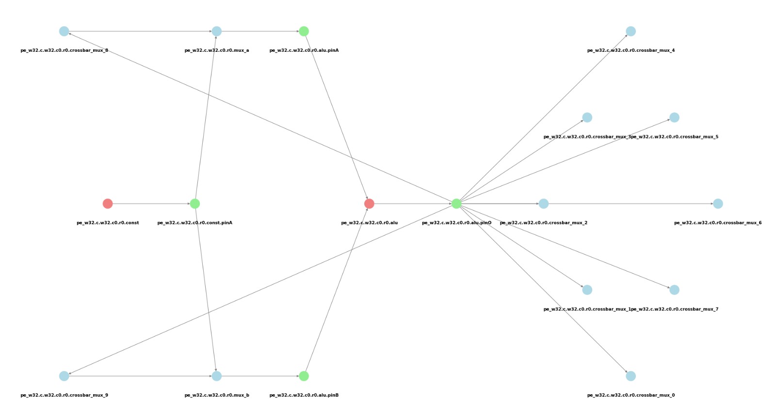
- Visualize ouput of RIKEN PE by device model gen script:
- Device model graph output file example:
33 [G_Name="LS.w32.c7.r5.memport", G_CellType=FuncCell, G_NodeType=MemPort, G_VisualX=7, G_VisualY="6.9"];
34 [G_Name="LS.w32.c7.r5.memport.inPinA", G_CellType=PinCell, G_NodeType=in, G_VisualX=7, G_VisualY="7.3"];
35 [G_Name="LS.w32.c7.r5.memport.outPinA", G_CellType=PinCell, G_NodeType=out, G_VisualX=7, G_VisualY="6.5"];
36 [G_Name="pe.w32.c1.r0.crossbar_mux_0", G_CellType=RouteCell, G_NodeType=Mux];
37 [G_Name="pe.w32.c1.r0.crossbar_mux_1", G_CellType=RouteCell, G_NodeType=Mux];
38 [G_Name="pe.w32.c1.r0.crossbar_mux_2", G_CellType=RouteCell, G_NodeType=Mux];
33 -> 35;
34 -> 33;
Required and optional attributes in device-model dot file:
- As shown above, vertices have specific attributes or properties. Some attributes are essential for UGRAMM to function correctly.
- G_Name: [Required] Contains the unique name of the cell in the device model graph.
- G_CellType: [Required] Contains the cell type (FuncCell, RouteCell, PinCell).
- G_NodeType: [Required] Contains the node type (e.g., for FuncCell, NodeTypes can include ALU, MEMPORT).
- G_VisualX: [Optional] X location for visualization purposes.
- G_VisualY: [Optional] Y location for visualization purposes.
- The [Required] node attributes must be clearly defined in the
device-model.dotfile when used as adfileinput to ensure that UGRAMM functions correctly.