Graph Vertex Generalization:
As outlined in the getting started guide, both the input application and hardware architecture are represented as graphs in UGRAMM. The vertex of the application graph (H) and device model graph (G) are designed to be versatile, making them applicable not only to CGRA applications but also adaptable to other use cases with minimal adjustments.
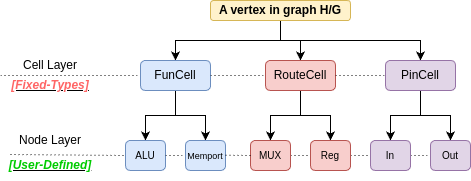
Any vertex in the graphs H or G must belong to one of the following CellType categories:
-
FuncCell: Represents a functional cell, typically performing operations such as arithmetic (e.g., ALU) or memory-related operations like load/store (e.g., IO/MemPort).
-
RouteCell: Represents a routing cell, such as a multiplexer (MUX) or register, which is crucial for connecting two
FuncCells within the hardware. -
PinCell: Represents a pin cell. Each functional cell must have defined input and output pins. For example, a 2-input ALU typically found in CGRA will have two input pins and one output pin in UGRAMM. UGRAMM utilizes these pins during the mapping process to manage properties such as commutativity when needed.
Note that for a vertex, the CellType must be either FuncCell, RouteCell, or PinCell, but the NodeType can be user-defined. In CGRA-type applications, it can be ALU or MemPort, while in FPGA-related applications, it can be LUT, DSP, etc. Both CellType [Fixed] and NodeType [Generalized] are parsed as attributes from the input graphs as follows (graphviz-dot-format):
Device-Model Vertex Examples:
- CellType : “FuncCell” :: NodeType : “MemPort”
0 [G_Name="LS.w32.c0.r0.memport", G_CellType=FuncCell, G_NodeType=MemPort];
- CellType : “FuncCell” :: NodeType : “ALU”
50 [G_Name="pe.w32.c1.r0.alu", G_CellType=FuncCell, G_NodeType=ALU];
- CellType : “PinCell” :: NodeType : “Pin”
49 [G_Name="LS.w32.c7.r5.memport.outPinA", G_CellType=PinCell, G_NodeType=out];
- CellType : “RouteCell” :: NodeType : “MUX”
20 [G_Name="pe.w32.c1.r0.crossbar_mux_0", G_CellType=RouteCell, G_NodeType=Mux];
- As demonstrated above, the device model can include all three types of cells defined in the
device-model-file.dotinput. This is explained in more detail in the device model file documentation.
Application-Graph Vertex Examples:
- As outlined in the application file input documentation, the application file defaults to having all vertices to be of
FuncCelltype. Other important attributes of this graph are also discussed there.